Transformer Inrush and Differential Protection Study
A three-phase electrical engineering study of transformer inrush, overexcitation, internal faults, external faults with CT saturation, and percentage-differential relay logic.
Project definition
Problem statement
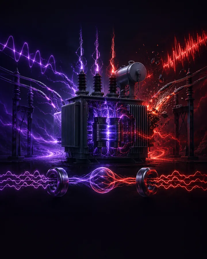
Transformer magnetising inrush can produce a large differential current even when the transformer is healthy. An internal winding fault can produce a similar operating-current magnitude, while an external fault can create spill current when one current transformer saturates.
The engineering problem is to combine percentage restraint, harmonic evidence, waveform shape, phase blocking, and fault-release logic while keeping both false trips and missed internal faults visible.
Project objectives
- Generate repeatable three-phase currents for six transformer operating and fault conditions.
- Measure fundamental, second-harmonic, fifth-harmonic, dwell, operate, and restraint quantities.
- Implement a dual-slope differential characteristic with blocking, memory, and high-current release.
- Test closing angle, residual flux, fault current, CT compression, frequency, thresholds, and noise.
- Report dependability, security, operation time, difficult cases, assumptions, and limitations.
Project structure
Project components
Waveform model
Generates referred primary and secondary currents for the six retained event classes.
Relay measurements
Calculates one-cycle harmonic RMS, operate current, restraint current, dwell fraction, and bipolarity.
Protection logic
Applies the dual-slope characteristic, harmonic and dwell blocks, cross-phase memory, release, and confirmation.
Experiment runner
Runs the baseline, inrush, fault, combined, threshold, frequency, and mixed-case studies.
Evidence package
Exports CSV, JSON, NPZ, figures, tests, references, and editable documentation.
Methodology
Project workflow
- 01Select an event
Choose one of the prepared transformer operating or fault conditions.
- 02Generate currents
The model creates three referred primary and secondary current channels on a common per-unit base.
- 03Measure windows
The relay calculates harmonic, operate, restraint, dwell, and bipolarity features.
- 04Apply protection logic
The characteristic, blocks, memory, release, and confirmation determine the event decision and time.
- 05Compare evidence
The retained tables and figures show correct outcomes, sensitivity, and the cases that remain difficult.
Demonstration scenario
The transformer is energised with residual flux and a difficult closing angle. The relay first blocks the inrush waveform. An internal fault is then introduced at 50 ms, and the high-current bipolar release allows a confirmed trip. The result is compared with inrush-only, internal-fault, and external-fault cases.
Engineering
Tools and method
- Tools
- The project uses Python, NumPy, Pandas, Matplotlib, Jupyter for subject analysis, simulation, and results.
- Waveforms
- Python and NumPy implement the per-unit time base, nonlinear inrush approximation, faults, overexcitation, and CT compression.
- Relay
- Transparent numerical functions implement Fourier measurements and stateful differential protection logic.
- Analysis
- Pandas retains every case and calculates dependability, security, balanced accuracy, timing, and feature summaries.
- Figures
- Matplotlib creates waveform, spectrum, characteristic, sweep, timing, and confusion-matrix figures.
- Verification
- Forty-three tests, branch coverage, dependency checks, a vulnerability audit, and release validation support the delivered result.
Testing
Evaluation
Evaluation measures
- Correct classification of all six reference scenarios
- Inrush security across 288 closing-angle, residual-flux, and peak-current cases
- Dependability across 96 internal faults and 63 faults beginning during inrush
- Security across 80 external faults with CT compression and ratio error
- Sensitivity to harmonic and dwell thresholds and off-nominal frequency
- Dependability, security, and balanced accuracy across 300 seeded mixed cases
Project boundaries
- All waveforms are synthetic educational evidence and not field recordings.
- The magnetic and CT models are transparent approximations and do not represent a named transformer, CT, or relay.
- The selected thresholds are study parameters and must not be used as field relay settings.
- A real protection study requires equipment data, network fault levels, manufacturer guidance, supervised injection tests, and review by a qualified protection engineer.
Included
- 01Three-phase transformer current waveform model
- 02Normal load, inrush, overexcitation, internal fault, external fault, and fault-during-inrush scenarios
- 03Percentage-differential, harmonic, dwell, cross-blocking, and high-current release logic
- 04Inrush, fault, threshold, frequency, and seeded mixed-case studies
- 051,219 retained result records and twelve labelled figures
- 06Forty-three automated tests with 99 percent core coverage
- 07Complete project files, models, calculations, and analysis material in a private GitHub repository
- 08A 74-page project report in PDF and editable Word formats
- 09A 17-page setup and usage guide in PDF and editable Word formats
- 10Fifty annotated references with literature-image provenance
Project record
No information is collected on this page.
- Permanent project ID
- GP-EE-1OWAPK3
- Catalogued
- 21 Aug 2026
- Completed
- 26 Aug 2026
- Verified
- 26 Aug 2026
- Demonstration
- Included in repository
Handover
After purchase
- 01Payment is confirmed
The project is marked unavailable and cannot be purchased again.
- 02Repository access is granted
The buyer's submitted GitHub account receives access to the private repository.
- 03The purchase record is delivered
The certification sheet is prepared from the reviewed buyer details and sent privately by email.