openEMS UWB antenna pulse-fidelity study
A completed openEMS study of printed UWB antenna impedance, bandwidth, mesh sensitivity, far-field phase, group delay, directivity, and pulse distortion from 3.1 to 10.6 GHz.
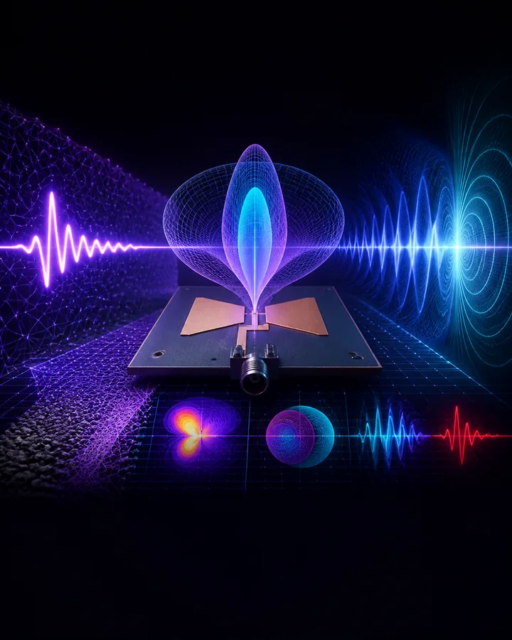
Project definition
Problem statement
A UWB antenna must provide useful impedance matching across a wide frequency range while preserving the phase of a short pulse.
The engineering problem is to compare a printed-monopole transition, quantify its frequency and pulse response, and determine whether the numerical result is stable enough to justify fabrication.
Project objectives
- Build a parameterized printed circular monopole in openEMS from 3.1 to 10.6 GHz.
- Compare a baseline, notched-ground candidate, and deliberately detuned transition at the same mesh setting.
- Test numerical sensitivity across four mesh densities and material sensitivity across three relative-permittivity values.
- Calculate S11, matched intervals, input impedance, directivity, group delay, and normalized pulse fidelity.
- State the simulation, convergence, fabrication, and measurement boundaries clearly.
Project structure
Project components
Antenna geometry
Defines the board, substrate, circular radiator, feed, partial ground, and notch with validated dimensions.
openEMS model
Builds the CSXCAD geometry, mesh, excitation, lumped port, boundaries, and near-field recording box.
Experiment runner
Executes the baseline, candidate, detuned, mesh, and dielectric cases under declared solver settings.
Frequency analysis
Calculates S11, matched intervals, input resistance, input reactance, and mesh comparisons.
Pulse analysis
Uses retained far-field phase to calculate group delay and normalized received-pulse fidelity.
Evidence package
Retains solver settings, compact arrays, exact metrics, figures, tests, references, and documentation.
Methodology
Project workflow
- 01Define geometry
Set the board, substrate, radiator, feed, ground, and notch dimensions in millimetres.
- 02Build the mesh
Create the declared free-space mesh and activate conductor edges and substrate layers.
- 03Run cases
Solve eight prepared cases over 151 frequency samples from 3.1 to 10.6 GHz.
- 04Calculate metrics
Derive matching, impedance, directivity, delay, and pulse-fidelity values from retained solver outputs.
- 05Check convergence
Compare the four mesh results before accepting any antenna-performance conclusion.
- 06Review evidence
Trace every rounded report value to the JSON, CSV, XML, NPZ, figure, or test evidence.
Demonstration scenario
Run the retained eight-case study, compare the baseline and candidate at the shared 28-cell mesh, inspect how the result changes at four mesh densities, and then connect the finest-mesh S11 and phase response to group delay and pulse fidelity. The nonmonotonic convergence result is retained as the main engineering limitation.
Engineering
Tools and method
- Tools
- The project uses openEMS 0.0.35, CSXCAD, Python, NumPy, Matplotlib, Jupyter for subject analysis, simulation, and results.
- Full-wave model
- openEMS 0.0.35 and CSXCAD implement the finite-difference time-domain antenna model.
- Geometry and experiment code
- Python dataclasses and solver adapters make the physical and numerical settings explicit.
- Analysis
- NumPy calculates frequency-domain and time-domain metrics from retained complex arrays.
- Figures
- Matplotlib produces the five labelled comparison, impedance, delay, and pulse figures.
- Reproducibility
- A pinned non-root Docker image supplies the solver and an automated test suite validates calculations and output structure.
Testing
Evaluation
Evaluation measures
- Matched-frequency sample coverage and contiguous matched intervals under a -10 dB S11 criterion
- Input resistance and reactance at 6.85 GHz
- Response variation across 20, 24, 28, and 32 cells per free-space wavelength
- Sensitivity to relative permittivity values of 3.28, 3.38, and 3.48
- Boresight group-delay mean and standard deviation
- Normalized pulse-fidelity factor and simulated maximum directivity
Project boundaries
- The package is a simulation study and does not contain measured antenna data.
- The retained mesh series is not converged, so the candidate is not fabrication-ready.
- The model does not include a connector launch, copper roughness, assembly variation, VNA calibration, chamber measurement, measured gain, or measured efficiency.
- Regulatory, fabrication, and product claims require a refined converged model and physical validation.
- No information collected.
Included
- 01Parameterized 30 by 45 mm printed circular monopole model
- 02Baseline, notched-ground candidate, and detuned comparison
- 03Four-level mesh study and three-value dielectric tolerance study
- 04S11, impedance, matched intervals, directivity, group delay, and pulse-fidelity analysis
- 05Eight retained solver cases with JSON, CSV, XML, and NPZ evidence
- 06Five generated result figures and 25 annotated references
- 0739 automated tests with 84 percent statement coverage
- 08Complete project files, models, calculations, and analysis material in a private GitHub repository
- 0994-page project documentation in PDF and editable Word formats
- 1013-page setup and usage guide in PDF and editable Word formats
Project record
No information is collected on this page.
- Permanent project ID
- GP-EC-1LCJ9AG
- Catalogued
- 21 Aug 2026
- Completed
- 25 Aug 2026
- Verified
- 25 Aug 2026
- Demonstration
- Included in repository
Handover
After purchase
- 01Payment is confirmed
The project is marked unavailable and cannot be purchased again.
- 02Repository access is granted
The buyer's submitted GitHub account receives access to the private repository.
- 03The purchase record is delivered
The certification sheet is prepared from the reviewed buyer details and sent privately by email.